
SCHWARZBECK PRODUCTS
• Accessories
• Antennas
• Antenna Adapter, Masts, Telescopes and Wheels
• Attenuators And Pulse Limiters
• Baluns
• Blocking Filters
• CDN´s
• CDNE
• Clamps: Abosorbing, Injection And Capacite Coupling Clamps
• Coaxial Cables
• Comb Generators / Reference Radiators
• Dummy Lamps
• Electromagnet
• Field Meters
• Helmhotz Coils / Radiating Loops
• LISN Line Impedance Stabilization Networks / AMN Artificial Mains Network
• BAN Broadband Artificial Networks Acc. To ISO 11452/7 Or DC-10614
• MagTest System
• Near Field Probes
• PLC – Devices Acc. To En 50561-1
• Preamplifiers
• Pulse Generators
• Striplines / TEM – Cells
• Spectrum Generator
• Used Equipment
• Van Der Hoofden Test Head
• Voltage Probes
SCHWARZBECK Company
SCHWARZBECK Data Sheets
SCHWARZBECK Product List
RELIANT EMC PRODUCT LINES
MANUFACTURERS
Request a Quote / Contact Us!
PLC - Devices Acc. To En 50561-1
• 50561 CABLES
• AC – Separator
• CS – 50
• CU 50561-1
• ISN 50561-1
• SPLIT 100
• SY 9223-50561-1
• SYMAT 40
Cables, terminations and connectors for EN 50561-1 testing. Scope of delivery see data sheet «Overview PLC measurement equipment»
![]() Overview PLC Measurement-System EN 50561-1
Overview PLC Measurement-System EN 50561-1
The AC separators provide connectivity between the LISNs and the device under test (DuT) respectively the auxiliary equipment (AE) as well as the connection to the measurement setup.
Two of the R/C elements required by the standard EN 50561-1 are already built in (1 M || 100 nF). Two identical AC separators are required for the measurement setup.
| Frequency range: | 1.6 MHz … 30 MHz |
| Symmetrical attenuation: (@ 100 Ω) |
max. 0.5 dB |
| Max RF voltage: | 10 V |
| Dieelctric strength each wire: | >1000 VDC |
| Test voltage between lines: | >1000 VDC |
| Max. power rating: | 1000 VA |
| Connector Mains plug: | CEE 7/7 |
| Connector Mains jack: | CEE 7/4 |
| Connections to the test circuit: | 4 mm safety laboratory jack |
| Housing dimensions: | |
| Length: | 68 mm |
| Width: | 112 mm |
| Hight: | 53 mm |
| Weight: | 310 g |
![]() Schwarzbeck AC Separator Data Sheet
Schwarzbeck AC Separator Data Sheet
![]() Overview PLC Measurement-System EN 50561-1
Overview PLC Measurement-System EN 50561-1
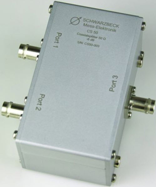
CS-50 is a resistive, unsymmetrical two way splitter with an impedance of 50 Ω It is part of the measurement setup according to EN 50561-1:2012 which is explained in chapter 9.2. Figure 4 shows the measurement setup with the available components.
| Frequency range: | DC … 30 MHz |
| Usable frequency range: | DC … >50 MHz |
| Insertion loss: | 6 dB ±0.2 dB |
| Frequency response: | <±0.1 dB |
| Nominal Impedance: | 50 Ω |
| Max. Input power: | 1 W |
| VSWR: | < 1.1:1 @ 30 MHz |
| Housing material: | Aluminium |
| Housing dimensions: | 125 x 104 x 50 mm |
| Weight: | ca. 280 g |
| Terminals: | BNC-female |
| Ground connectors: | Bottom of case and 4 mm laboratory jack |
![]() Schwarzbeck CS-50 Unsymmetrical Splitter Data Sheet
Schwarzbeck CS-50 Unsymmetrical Splitter Data Sheet
![]() Overview PLC Measurement-System EN 50561-1
Overview PLC Measurement-System EN 50561-1
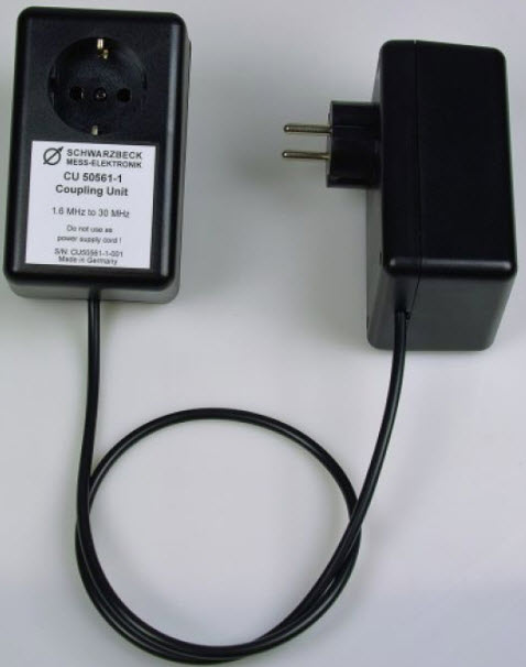
The coupling unit CU 50561-1 belongs to the equipment for measurements at powerline transmission devices. The specifications for the measurements at PLC devices are included within the standard EN-50561-1.
Combined with two line impedance stabilization networks (LISN) the coupling unit provides a coupling system which guarantees defined conditions for the measurement.
| Frequency range: | 1.6 MHz … 30 MHz |
| Symmetrical attenuation: (@ 25 Ω) |
40 dB ± 1.5 dB |
| Max RF voltage: | 10 V |
| Dieelctric strength each wire: | >1000 VDC |
| Test voltage between lines: | >1000 VDC |
| Max. power rating: | 1000 VA |
| Connector Mains plug: | CEE 7/7 |
| Connector Mains jack: | CEE 7/4 |
| Cable length: | ~800 mm |
| Housing dimensions: | |
| Length: | 68 mm |
| Width: | 112 mm |
| Hight: | 53 mm |
| Weight: | 310 g |
![]() Overview PLC Measurement-System EN 50561-1
Overview PLC Measurement-System EN 50561-1
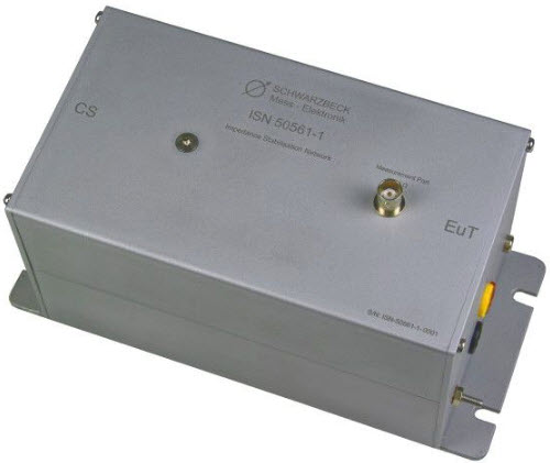
ISN 50561-1 is an impedance stabilization network (ISN) for measurements of asymmetrical disturbance voltage of power line communication equipment. This ISN is built according to the standard EN 50561-1:2012, Annex B, Figure B.1.
| Frequency range: | 1.6 MHz … 30 MHz |
| Max. current: | 16 A |
| Max. operating voltage: | 250 VAC @50/60 Hz |
| Proof voltage L / N to housing: | >1000 VDC |
| Measurement port: | BNC jack 50 Ω |
| Connectors EUT, CS: | 4 mm safety laboratory jacks |
| Length: | 225 mm |
| Width: | 120 mm |
| Hight: | 105 mm |
| Weight: | ~1300 g |
![]() Schwarzbeck ISN 50561-1 Impedance Stabilization Network for PLC Data Sheet
Schwarzbeck ISN 50561-1 Impedance Stabilization Network for PLC Data Sheet
![]() Overview PLC Measurement-System EN 50561-1
Overview PLC Measurement-System EN 50561-1
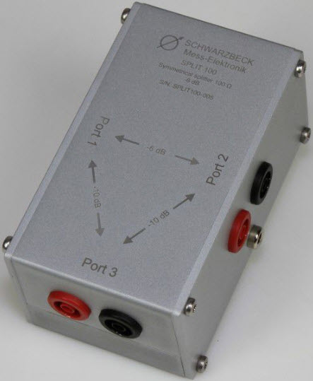
SPLIT 100 is a resistive, symmetrical two port splitter with an impedance of 100 Ω.
It is part of the measurement setup according to EN 50561-1:2012 which is explained in chapter 9.2. Figure 4 shows the measurement setup.
| Frequency range: | DC … 30 MHz |
| Usable frequency range: | DC … >50 MHz |
| Insertion loss: | 6 dB ± 0.2 dB |
| Frequency response: | > +/-0.5 dB |
| Nominal Impedance: | 100 Ω |
| Max. Input power: | 1 W |
| Proof voltage against housing: | >500 VDC |
| Terminals: | 4 mm safety laboratory jack |
| Length: | 125 mm |
| Width: | 104 mm |
| Hight: | 50 mm |
| Weight: | ca. 270 g |
![]() Schwarzbeck SPLIT 100 Symmetrical Splitter Data Sheet
Schwarzbeck SPLIT 100 Symmetrical Splitter Data Sheet
![]() Overview PLC Measurement-System EN 50561-1
Overview PLC Measurement-System EN 50561-1
![]()
SY 9223-50561-1 is a symmetrical transformer which provides impedance transformation and a specified insertion loss. It transforms an unsymmetrical 50 Ω signal into a symmetrical signal with an impedance of 100 Ω and attenuates the power by 8 dB. It belongs to a measurement setup according to EN 50561-1:2012, chapter 9.2. Figure 4 shows the setup, figure 5 shows the principle diagram.
| Frequency range: | 1.6 MHz … 30 MHz |
| Insertion loss: | 8 dB ± 0.2 dB |
| Symmetrical impedance: | 100 Ω |
| Unsymmetrical impedance: | 50 Ω |
| Max. input power: | 200 mW |
| Proof voltage against housing: | >500 VDC |
| Unsymmetrical connector: | BNC jack 50 Ω |
| Symmetrical terminals: | 4 mm safety laboraty jack |
| Length: | 125 mm |
| Width: | 104 mm |
| Hight: | 50 mm |
| Weight: | ca. 270 g |
![]() Overview PLC Measurement-System EN 50561-1
Overview PLC Measurement-System EN 50561-1
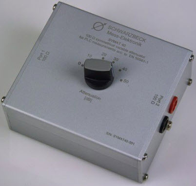
SYMAT 40 is a symmetrical 100 Ω step attenuator. It is switchable between 0 dB, 10 dB, 20 dB, 30 dB, 40 dB and 50 dB.
It’s purpose is to gather properties of the dynamic performance control of PLC/PLT devices. The measurement setup is described in the standard EN 50561-1:2012 chapter 9.2. Figure 4 shows the setup.
| Frequency range: | DC … 30 MHz |
| Usable frequency range: | DC … >50 MHz |
| Nominal impedance: | 100 Ω |
| Attenuator steps: | 0, 10, 20, 30, 40, 50, dB |
| Frequency response: | <0.5 dB |
| Max. input power: | 1 W |
| VSWR: | < 1.5:1 @ 30 MHz |
| Proof voltage against housing: | >500 VDC |
| Connectors: | 4 mm safety laboratory jack |
| Length: | 125 mm |
| Width: | 104 mm |
| Hight: | 50 mm |
| Weight: | ca. 470 g |