
SCHWARZBECK Helmholtz Coils
SCHWARZBECK PRODUCTS
• Accessories
• Antennas
• Antenna Adapter, Masts, Telescopes and Wheels
• Attenuators And Pulse Limiters
• Baluns
• Blocking Filters
• CDN´s
• CDNE
• Clamps: Abosorbing, Injection And Capacite Coupling Clamps
• Coaxial Cables
• Comb Generators / Reference Radiators
• Dummy Lamps
• Electromagnet
• Field Meters
• Helmhotz Coils / Radiating Loops
• LISN Line Impedance Stabilization Networks / AMN Artificial Mains Network
• BAN Broadband Artificial Networks Acc. To ISO 11452/7 Or DC-10614
• MagTest System
• Near Field Probes
• PLC – Devices Acc. To En 50561-1
• Preamplifiers
• Pulse Generators
• Striplines / TEM – Cells
• Spectrum Generator
• Used Equipment
• Van Der Hoofden Test Head
• Voltage Probes
SCHWARZBECK Company
SCHWARZBECK Data Sheets
SCHWARZBECK Product List
RELIANT EMC PRODUCT LINES
MANUFACTURERS
Request a Quote / Contact Us!
Radiating Loops And Coils
• FESP 5133 – Circular Screen Coil
• FESP 5133-F – Circular Screen Coil
• FESP 5133-9 – Circular Screen Coil
• FESP 5133-1330 – Circular Coil Radiating Loop
• FESP 5134-1 – Field Monitoring Loop
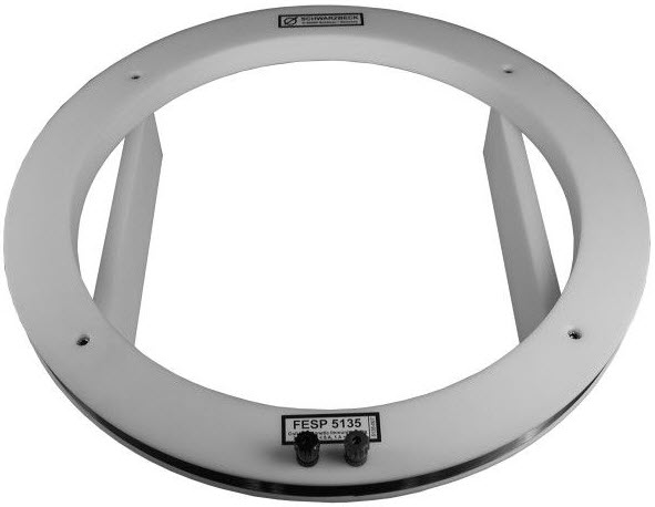
• FESP 5135 – Circular unshielded Coil
• FESP 5210-1 – Square Induciton Coil
• FESP 5410-1 – Square Induciton Coil
• MFPO 9760 – Current Transformer and Pulse Generator
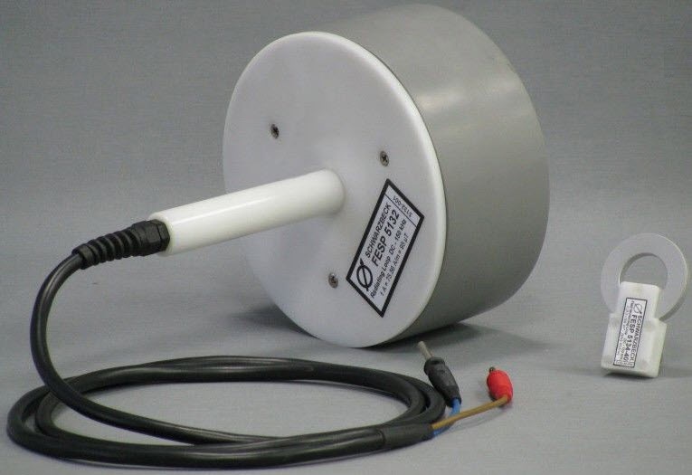
· Radiating loop
· Diameter 12 cm
· 20 turns
· 15 Hz to 150 kHz
· max 15 A
· 2x Banana jack 4mm
according to ISO 11452-8, MIL-STD 461E RS101, EN 55103 5.18.3.2
![]() Schwarzbeck FESP 5132 Data Sheet
Schwarzbeck FESP 5132 Data Sheet
![]() Schwarzbeck FESP 5132 Security Notes
Schwarzbeck FESP 5132 Security Notes
Option:
Option LoopHolder50:
Calibration fixture to hold FESP 5134-40 in FESP 5132 in a distance of 50 mm according to MIL461E figure RS101-3.
![]() Schwarzbeck LoopHOLDER50 Data Sheet
Schwarzbeck LoopHOLDER50 Data Sheet
FESP 5133 Loop Sensor / Antenna
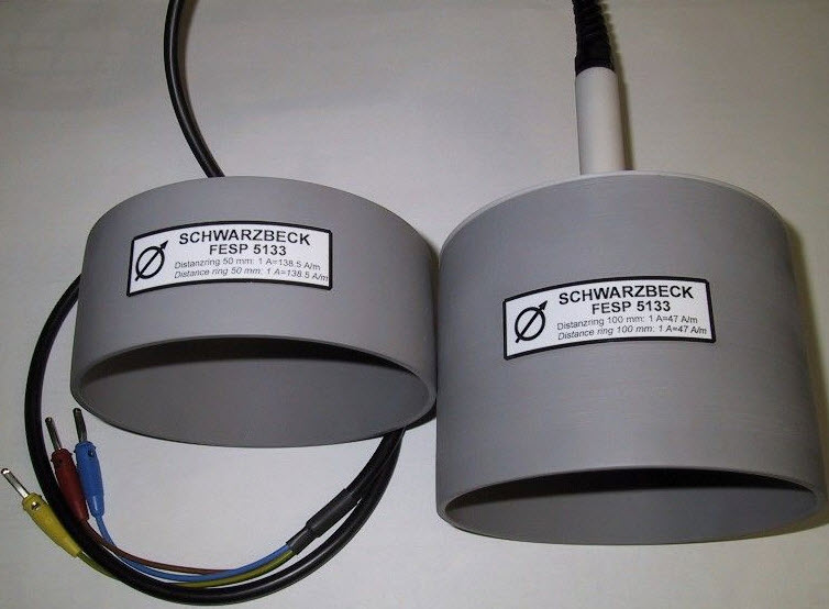
· Loop Sensor / Antenna
· 36 turns in 4 layers
· Diameter 133 mm
· EN 55103-1 A.2.b
· EN 55103-2 A.4.1
· 0 – 200 kHz
· banana plugs (standard) or BNC connector female
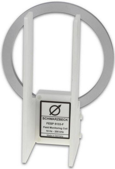
The Loop Sensor FESP 5133-F was designed to monitor the generated magnetic fields in radiated susceptibility tests. There is nearly no difference to the FESP 5133-7/41, which was originally designed for MIL-STD461E and previous versions, in which the RF-litz wire type AWG 7/41 was specified. Recent versions of MIL-STD461 F and G require a resistance between 5 Ω to 10 Ω for the loop sensor instead. This new requirement was met by the use of a suitable RF-litz wire, which provides a resistance of 7.2 Ω for the FESP 5133-F.
![]() Data Sheet FESP 5133-F
Data Sheet FESP 5133-F
FESP 5133-9 Circular screened Coil
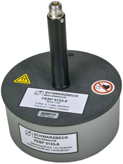
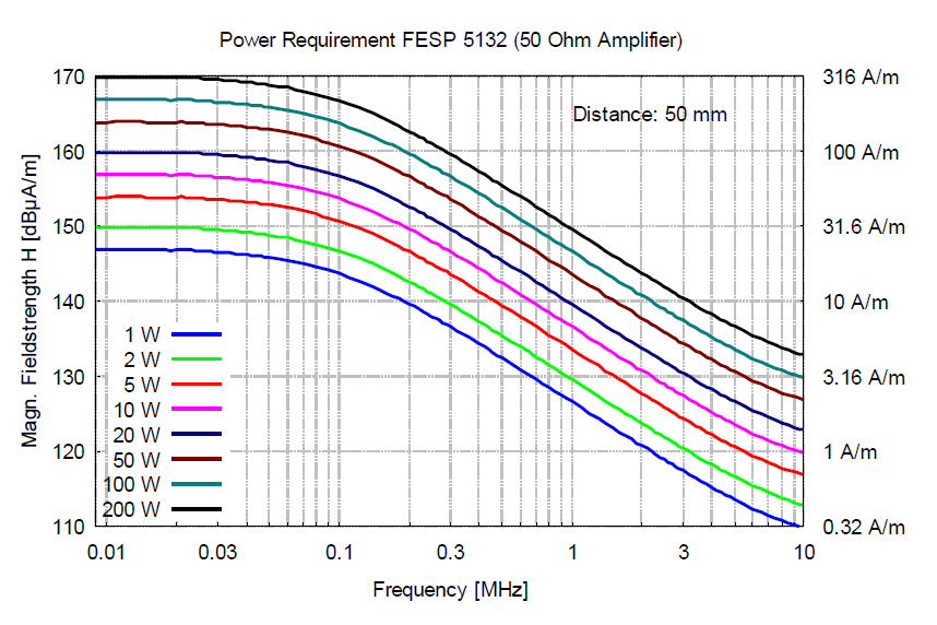
The magnetic, handheld coil FESP 5133 was designed to generate defined magnetic field strength in the audio frequency range up to 3 MHz. The main application is immunity testing against magnetic fields according to VG 95377 Part 13 and many others. Depending on the current source characteristics magnetic fields up to 400 A/m can be generated for a short time. There are further rings available on request in order to provide a certain scaling between coil current and magnetic field strength (e.g. 1 Amp coil current = 10 A/m field strength).
Application as magnetic field probe:
The FESP 5133-9 can also be used to measure existing magnetic fields. The open circuit output voltage is directly proportional to the magnetic field strength (at fixed frequency) or directly proportional to frequency (at constant magnetic field strength).
| Number of turns: | 9 |
| Wire diameter: | 1.2 mm Cu |
| Maximum coil current: | 11 A (5 min.) |
| Nominal coil current: | 7 A continuous |
| Max. magn. field strength: | 380.4 A/m (5 min.) |
| Nominal magn. field strength: | 242 A/m continuous |
| Magnetic field strength, 1 A coilcurrent: (with 50 mm distance ring): | 34.58 A/m |
| Current required for 1 A/m: (with 50 mm distance ring) |
28.9 mA |
| Flux density with 50 mA at 50 mm distance: | 127 dBpT |
| Inner coil diameter: | 133 mm |
| Medium coil diameter: | 134.2 mm |
| Spacing coil center to measurement plane: | 50 mm |
| Mechanical dimensions: | 0.16 m x 0.2 m |
| Connector: | N-jack |
| Usable frequency range: | 10 kHz – 3 MHz |
| Inductance: | ~ 20 μH |
| Resistance: | 0.1 Ω |
| Weight: | 0.8 kg |
| Standard: | VG 95377 Part 13 |
![]() Schwarzbeck FESP 5133-9 Circular screened Coil Data Sheet
Schwarzbeck FESP 5133-9 Circular screened Coil Data Sheet
FESP 5133-1330 Circular Radiating Loop
· Circular radiating loop for extremely high field strength up to several mT
· 225 turns
· according to SF 01 G
· VG95377
FESP 5134-1 Magnetic Field Sensor / Field Monitoring Loop
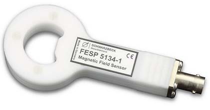
The magnetic, handheld field sensor coil FESP 5134-1 was designed to determine the magnetic fieldstrength during immunity tests. The loop sensor consists of a single shielded turn and can be used up to 400 MHz. The FESP 5134-1 is intended to be used with 50 Ω measuring equipment, e.g. spectrum analyzers or measuring receivers. Thanks to the shielded turn the loop sensor achieves high symmetry and good E-field rejection. Typical appli-cations are immunity tests acc. IEC 61000-4-39, several automotive standards, the measurement of human exposure limits acc. to ICNIRP, IEEE C.95-2005, 26.BImSchV and many others.
| Number of Turns: | 1 |
| Coil Diameter: | 40 mm |
| Usable Frequency Range: | 10 kHz – 400 MHz |
| Nominal Frequency Range: | 100 kHz – 300 MHz |
| Inductance: | ca. 125 nH |
| Weight: | ca 70 g |
| Dimensions: | 46 x 18 x 95 mm |
| Connector: | BNC |
Option: LoopHolder50-39 – Calibration jig to hold FESP 5139 in a distance of 50 mm from FESP 5134-1 acc. to IEC 61000-4-39
![]() Schwarzbeck FESP 5134-1 – Magnetic Field Sensor / Field Monitoring Loop Data Sheet
Schwarzbeck FESP 5134-1 – Magnetic Field Sensor / Field Monitoring Loop Data Sheet
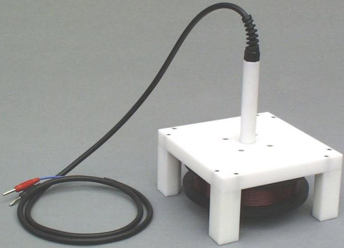
· Radiating coil
· Diameter 0.5 m
· 20 turns in one layer
· according to EN 55103-2 A.3.1
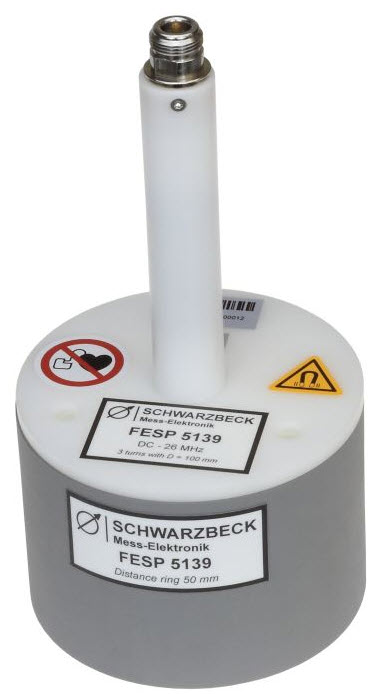
The magnetic, handheld coil FESP 5139 was designed to generate defined mag-netic fieldstrength in the frequency range from DC up to 26 MHz. The main application is immunity testing against magnetic fields according to IEC 61000-4-39. Depending on the current source char-acteristics magnetic fields up to 360 A/m can be generated for a short time. The generated magnetic fieldstrength is pro-portional to the coil current. A distance ring allows a precise spacing of 50 mm between coil and EUT surface. Other distance rings can be used to scale the current-fieldstrength ratio. The highest fieldstrength levels can be achieved using the shortest ring. There are further rings available on request in order to provide a certain scaling between coil current and magnetic fieldstrength (e.g. 1 A coil current = 20 A/m fieldstrength).
Application as Sensor for Magnetic Fields:
The FESP 5139 can also be used to measure existing magnetic fields. For this purpose the FESP 5139 is connected to a frequency selective 50 Ohm measuring instrument e.g. a spectrum analyzer or a measuring receiver.
| Number of turns: | 3 |
| Wire diameter: | 1 mm Cu |
| Maximum Coil Current: | 12 A (5 min.) |
| Nominal Coil Current: | 8 A continuous |
| Maximum magnetic Field Strength:(without distance ring, in coil center) | 360 A/m (5 min.) |
| Nominal Magnetic Field Strength with 50 mm distance ring: | 85 A/m continuous |
| Magnetic Fieldstrength, 1 A Coil Current: (with 50 mm distance ring) |
10.61 A/m |
| Current required for 1 A/m: (with 50 mm distance ring) |
94.25 mA |
| Medium coil diameter: | 100 mm |
| Spacing coil center to measurement plane: | 50 mm |
| Mechanical Dimensions: | 11 x 11 x 21 cm |
| Connector: | N-female |
| Usable Frequency Range: | 0 – 26 MHz |
| Inductance: | 2.3 μH |
| Weight: | 0.47 kg |
Option: LoopHolder50-39 – Calibration jig to hold FESP 5139 in a distance of 50 mm from FESP 5134-1 acc. to IEC 61000-4-39
![]() Schwarzbeck FESP 5139 Radiating Loop Data Sheet
Schwarzbeck FESP 5139 Radiating Loop Data Sheet
FESP 5210-1 – Square Induciton Coil
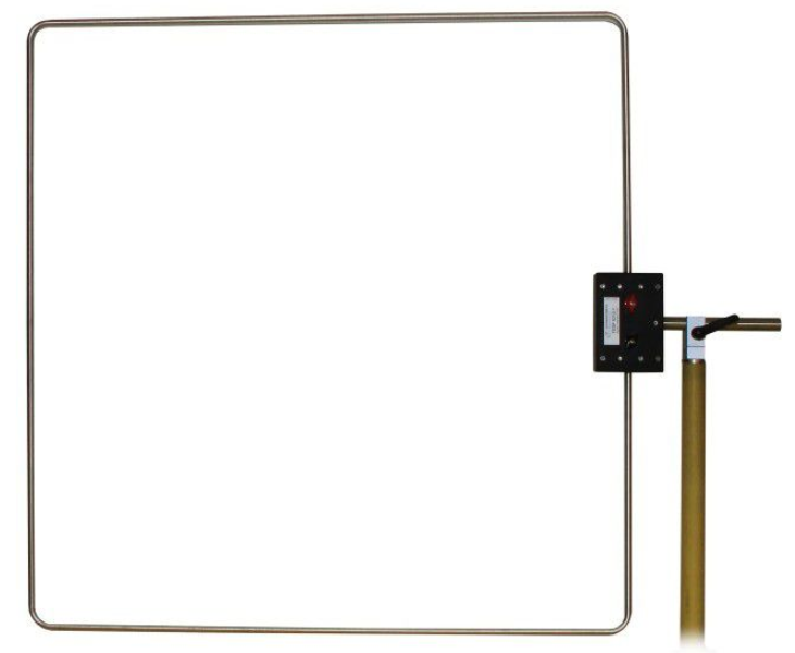
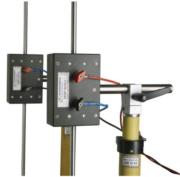
The square induction coil FESP 5210-1 is used to generate magnetic fields for immunity testing according to IEC 61000-4-8, IEC 61000-4-9 and IEC 61000-4-10. The edge length of the square shaped coil is 1 m. The coil comes with wing terminals, which allow a versatile and simple connection to the current source.
Operation as Helmholtz Coil:
Two square induction coil FESP 5210-1 can be combined to form a Helmholtz coil pair. The main advantages of a Helmholtz coil pair is an increase of fieldstrength and a significant improve- ment of field uniformity. For this purpose the coil planes are aligned in parallel. Electrically the coils have to be wired in series, keeping in mind that the current through the coils must flow in the same direction. This is very important to obtain the wanted addition of both fieldstrength contributions in the volume between the coils.
| Frequency range: | DC … 10 MHz |
| Edge length: | 1 m +/- 1 % |
| Number of turns: | 1 |
| Max. cont. current: | 100 A |
| Max. current (10 min): | 150 A |
| Max. current (1 min): | 200 A |
| Max. cont. fieldstrength (coil center): |
90 A/m |
| Inductance: | 3.4 µH |
| Self resonance: | 16 MHz |
| Material / diameter: | Aluminium 12 mm |
| Mounting tube: | 22 x 195 mm |
| Weight: | 1.5 kg |
| Connector: | 4 mm wing terminals |
| Standard: | IEC 61000-4-8 IEC 61000-4-9 IEC 61000-4-10 |
![]() Schwarzbeck FESP 5210-1 – Square Induciton Coil Data Sheet
Schwarzbeck FESP 5210-1 – Square Induciton Coil Data Sheet
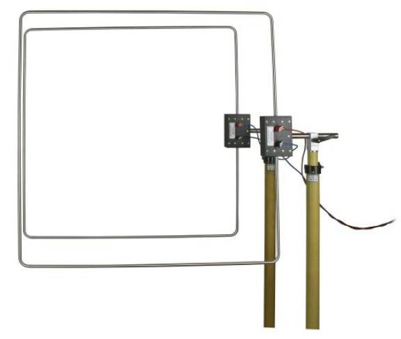
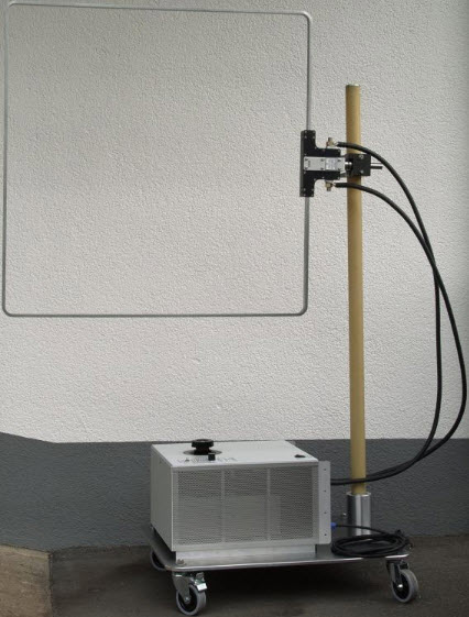
FESP 5410-1 – Square Induciton Coil 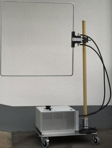
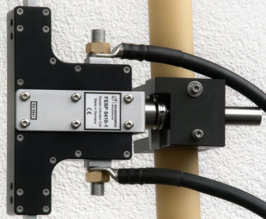
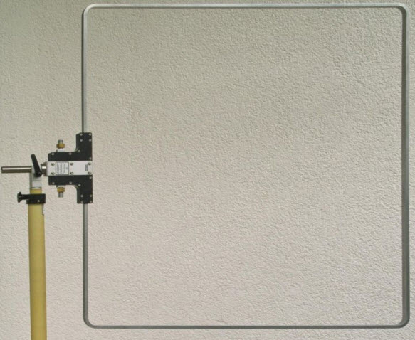
The square induction coil FESP 5410-1 is used to generate magnetic fields for immunity testing according to IEC 61000-4-8, IEC 61000-4-9 and IEC 61000-4-10. The side length of the square shaped coil is 1 m. The coil comes with screw terminals.
Operation as Helmholtz Coil: Two square induction coil FESP 5410-1 can be combined to form a Helmholtz coil pair. The main advantages of a Helmholtz coil pair is an increase of fieldstrength and a significant improvement of field uniformity. For this purpose the coil planes are aligned in parallel. Electrically the coils have to be wired in series, keeping in mind that the current through the coils must flow in the same direction. This is very important to obtain the wanted addition of both fieldstrength contributions in the volume between the coils.
![]() Schwarzbeck FESP 5410-1 – Square Induciton Coil Data Sheet
Schwarzbeck FESP 5410-1 – Square Induciton Coil Data Sheet
MFPO 9760 – Current Transformer and Pulse Generator 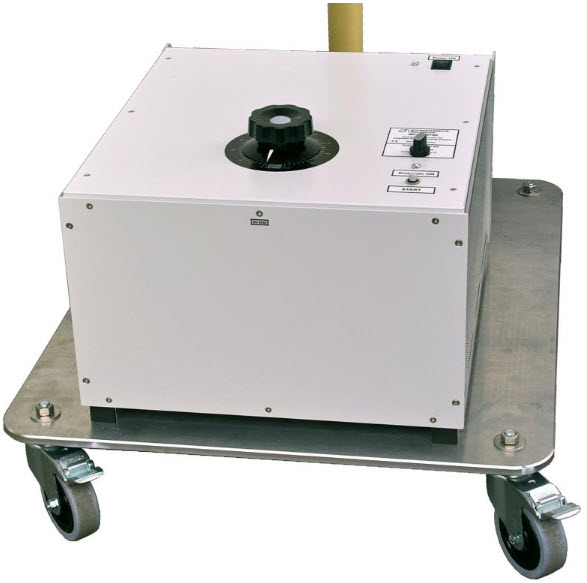
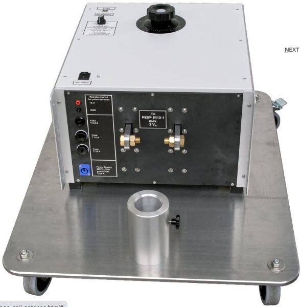
The MFPO 9760 is a current transformer for the typical mains frequencies of 50 Hz / 60 Hz. It is used to feed the 1 m square induction coil FESP 5410-1. This coil can reach magnetic field strengths of 1000 A/m for short time and 360 A/m continuously in its center. As this coil has only one turn it has relatively low inductance and can be used for fast signals in the time domain. On the other hand a one turn coil has a low coil factor and needs to be driven with hundreds of Ampere to reach the fields expected by IEC 61000-4-8.
The pulse generator which is built into MFPO 9760 allows defined “ON intervals” of 0.5…5.0 seconds. Other time intervals can be set by manually holding the start button longer. Alternatively the interval can be set usiing the remote input.
![]() MFPO 9760 – Current Transformer and Pulse Generator Data-Sheet
MFPO 9760 – Current Transformer and Pulse Generator Data-Sheet